Windows Server 2008 R2 Unleashed (240 page)
Read Windows Server 2008 R2 Unleashed Online
Authors: Noel Morimoto
serves up static pages, can respond to a single client’s requests from multiple nodes in the
NLB cluster. For a web-based application, such as an e-commerce application, an
encrypted SSL session, or an application that is authenticated by the actual web server, the
NLB cluster would need to direct all communication between the client and a specific
cluster node. Considering these types of scenarios in advance helps determine how the
NLB cluster will be defined.
1216
CHAPTER 29
System-Level Fault Tolerance (Clustering/Network Load Balancing)
Installing the Network Load Balancing Feature
Before an NLB cluster can be created, the feature needs to be installed on all servers that
will participate in the cluster. To install the Network Load Balancing feature, perform the
following steps:
1. Log on to each Windows Server 2008 R2 system with an account that has local
administrator rights.
2. Click Start, click All Programs, click Administrative Tools, and select Server Manager.
3. In the tree pane, select Features, and in the Actions pane, click the Add Features link.
4. On the Before You Begin page, click Next to continue.
5. On the Add Features page, check the box for Network Load Balancing, and click
Next to continue.
6. On the Confirm Installation Selections page, review the list of features that will be
added, and click Install to begin the installation.
7. On the Installations Results page, review the results, and click Close to return to
Server Manager.
8. Close the Server Manager console and log off of the server.
9. Log on and repeat this process on the remaining servers that will participate in the
ptg
cluster as required.
Creating Port Rules
When an NLB cluster is created, one general port rule is also created for the cluster. The
NLB cluster port rule or rules define what type of network traffic the cluster will load-
balance across the cluster nodes and how the connections will be managed. The Port Rules
Filtering option defines how the traffic will be balanced across each individual node. As a
best practice, limiting the allowed ports for the clustered IP addresses to only those needed
by the cluster load-balanced applications can improve overall cluster performance and
security. In an NLB cluster, because each node can answer for the clustered IP address, all
inbound traffic is received and processed by each node. When a node receives the request,
it either handles the request or drops the packet if another node has already established a
session or responded to the initial request.
When an administrator discards the default NLB cluster port rule and creates a rule that
only allows specific ports to the clustered IP address or addresses, plus an additional rule
to block all other traffic destined for the cluster IP address, each cluster node can quickly
eliminate and drop packets that do not meet the allow port rule and in effect improve
network performance of the cluster. The security benefit of this configuration also removes
any risk of attacks on any other port using the cluster IP address.
Port Rules Filtering Mode and Affinity
Within an NLB cluster port rule, the NLB administrator must configure the appropriate
filtering mode. This allows the administrator to specify whether only one node or multi-
ple nodes in the cluster can respond to requests from a single client throughout a session.
There are three filtering modes: Single Host, Disable This Port Range, and Multiple Host.
Deploying Network Load Balancing Clusters
1217
Single Host Filtering Mode
The Single Host filtering mode ensures that all traffic sent to the cluster IP address that
matches a port rule with this filtering mode enabled is handled exclusively in the cluster
by one particular cluster node.
Disable This Port Range Filtering Mode
The Disable This Port Range filtering mode tells the cluster which ports are not active on
the cluster IP address. Any traffic requests received on the cluster IP address that match a
port rule with this filtering mode result in the network packets getting automatically
discarded or dropped. Administrators should configure specific port rules and use this
filter mode for ports and port ranges that do not need to be load-balanced across the
cluster nodes.
Multiple Hosts Filtering Mode
The Multiple Host filtering mode is probably the most commonly used filtering mode and
is also the default. This mode allows traffic to be handled by all the nodes in the cluster.
When traffic is balanced across multiple nodes, the application requirements define how
the Affinity mode should be set. There are three types of multiple host affinities:
.
None—
This affinity type can send unique clients’ requests to all the servers in the
cluster during the entire span of the session. This can speed up server response times
ptg
but is well suited only for serving static data to clients. This affinity type works well
for general web browsing, read-only file data, and FTP servers.
.
Network—
This affinity type routes traffic from a particular class C address space to
a single NLB cluster node. This mode is not used too often but can accommodate
client sessions that use stateful applications and when different client requests are
serviced by down-level proxy servers. This is a useful affinity type for companies that
direct traffic from several remote offices, through proxies before connecting to the
services, and/or applications managed by the port rules in the NLB cluster.
.
Single—
This affinity type is the most widely used. After the initial request is
received by the cluster nodes from a particular client, that node will handle every
request from that client until the session is completed. This affinity type can accom-
modate sessions that require stateful data such as an encrypted SSL web application
29
or a Remote Desktop session. This is the default filtering mode on a port rule and is
well suited to handle almost any NLB clustered service or application.
Using Cluster Operation Mode
There are three different cluster operation modes: Unicast, Multicast, and IGMP Multicast.
Most traditional network traffic is unicast traffic where clients and servers maintain a one-
to-one network connection. Multicast networking allows a server to send out information
to one multicast address that is then processed by a number of clients. To receive multi-
cast data, a client joins a multicast group associated with the multicast address and one
data feed or transmission is presented to the group by the server, thereby streamlining and
improving network performance of the application. Multicast traffic is usually one direc-
tion and when the multicast client joins the group, it begins to receive the transmission.
1218
CHAPTER 29
System-Level Fault Tolerance (Clustering/Network Load Balancing)
Common applications that use multicast are streaming music and video websites, Internet
radio, and Internet training or online noninteractive courses. IGMP Multicast can be used
in place of multicast and enhances overall network performance when multicast is
required. Selecting this management protocol allows for the multicast clients to register
with the IGMP Multicast server and afterward, the multicast traffic will only be sent to the
switch ports or trunks that connect to the multicast clients, reducing traffic on the
remaining ports of the network switches. One more important point to mention about
multicast traffic is that the network switches and routers that the traffic will pass through
must support multicast traffic and allow it. Many enterprise class switches and routers
have multicast support disabled by default.
Configuring Network Cards for NLB
Configuring the network cards on the NLB cluster nodes is the first step in building the
cluster. Although these steps can be performed during cluster creation using the NLB
Manager, the same result can be achieved by editing the TCP/IP properties of each of the
cluster node’s network cards. Best practice for NLB cluster nodes running in Unicast mode
is to have two network cards to allow host communication to occur on one NIC while
cluster communication is isolated on the cluster NIC. Multiple NICS can also add greater
flexibility when it comes to controlling traffic and managing network security.
ptg
Creating an NLB Cluster
Before an NLB cluster can be created, a few bits of information are required. The NLB
cluster is actually clustering based on a defined IP address, the DNS name, and the TCP/IP
ports that will be used. Each NLB cluster node can also be configured with multiple
network cards. Each card can be associated with a different NLB cluster and a single card
can support multiple clusters, but each cluster must have a different DNS name and IP
address(es). One configuration that cannot be performed is creating a single NLB cluster
that uses multiple network adapters in a single node. To designate multiple adapters for a
single NLB cluster, third-party network teaming software must be loaded prior to configur-
ing the NLB cluster; the cluster will use the Virtual Team Network adapter and the teamed
physical adapters should not be configured with NLB. For this example, a new NLB cluster
will be created for the name www.companyabc.com using the IP address of
192.168.206.50. To create an NLB cluster, perform the following steps:
1. Log on to a Windows Server 2008 R2 system with an account that has local adminis-
trator rights and that has the NLB feature already installed.
2. Click Start, click All Programs, click Administrative Tools, and select Network Load
Balancing Manager.
3. When the Network Load Balancing Manager console opens, click the Cluster menu,
and select New to create a new cluster.

Deploying Network Load Balancing Clusters
1219
4. When the New Cluster window opens, type in the name of the first server that will
be added to the new NLB cluster, and click Connect. If the server is a remote system
and cannot be contacted, ensure that the Inbound Remote Administration exception
has been enabled in the remote system’s firewall.
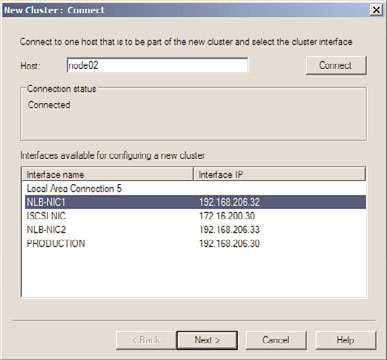
5. When the server is contacted, each of the network adapters will be listed, select the
adapter that will be used for the NLB cluster, as shown in Figure 29.16, and click Next.
ptg
FIGURE 29.16
Selecting the network adapter that will be used for the NLB cluster.
6. On the Host Parameters page, accept the defaults of giving this first server the Host
ID of 1 and select the dedicated IP address that will be used when communication
is received for the NLB cluster IP address, which will be specified next. Click Next
to continue.
7. On the Cluster IP Addresses page, click the Add button to specify an IPv4 address
and subnet mask or an IPv6 address to use for the NLB cluster, and click OK. For our
example, we will use the IPv4 configuration of 192.168.206.50/255.255.255.0.
29
8. Back on the Cluster IP Addresses page, add additional cluster IP addresses as
required, and click Next to continue.
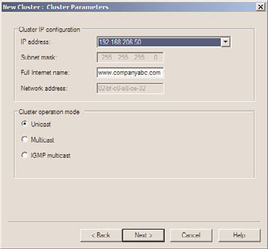
9. On the Clusters Parameters page, enter the fully qualified DNS name that is associ-
ated with the IP address specified on the previous page, and select whether it will be
used for Unicast traffic, Multicast traffic, or IGMP Multicast. This choice depends on
the network communication of the service or application that will be used in this
NLB cluster. For this example, we are creating an NLB cluster for standard web
traffic, so we will use www.companyabc.com as the Internet name and select Unicast
as the cluster operation mode, as shown in Figure 29.17.
