An Introduction to Rowing (4 page)
Read An Introduction to Rowing Online
Authors: HL Fourie
Gearing = 2 x outboard length / span = 2 x (overall oar length - inboard length) / span
The gearing is adjusted by moving the collar inward or outward along the sleeve of the oar. The collar retaining clamp is loosened using a screwdriver and then collar is moved to an adjacent notch on the sleeve. The clamp is then tightened again. Moving the collar outward decreases the gearing and reduces oar load.
A CLAM or Clip-on Load Adjustment Method is a temporary shim that clips over the sleeve of an oar on the outboard side of the collar to reduce the gearing or load of an oar. Since the CLAM is between the collar and the oarlock, this increases the inboard length, decreases the outboard length and thereby reduces the gearing and makes the boat easier to row. A single CLAM has a width of 1 cm. It is convenient to use CLAMs when testing different oar loadings with a crew without having to come off the water to adjust the collars.
The rigger consists of a frame and the oarlock. The rigger frame is bolted to the shell's gunwales. There are different types of riggers.
- Three-point rigger. This rigger has three points of attachment to the gunwale: the fore-stay, the main stay and the back stay.
- Two-point rigger. This rigger has two points of attachment to the gunwale: the main stay and the back stay.
- Wing rigger. A wing rigger that consists of an aluminum wing and a bracing strut called a backstay is shown below.

Figure 18:
Three-point Rigger
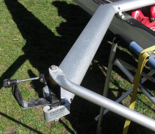
Figure 19:
Wing Rigger
It is the responsibility of the crew to rig the shell. Riggers are bolted to the gunwales using 7/16 inch hex-bolts in the USA and 11 mm hex-bolts in Europe. The picture below shows a starboard backstay and a port wing rigger bolted to the gunwale.

Figure 20:
Rigger Attachment
A starboard wing rigger and backstay that have been detached from the shell are shown below.
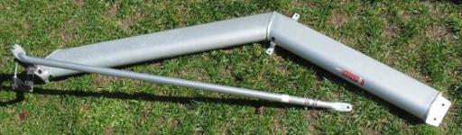
Figure 21:
Wing Rigger
The oarlock actually holds the oar. The oarlock swivels on a pivot pin that is attached to the rigger frame. The oarlock is made up of the U-shaped swivel which rotates on the pin, the gate which is a metal bar that opens up to allow the oar to be inserted into the oarlock and a star locking nut at the end of the gate to ensure that the gate remains closed. Loosen the locking nut to open the gate, insert the sleeve of the oar into the oarlock, and then close the gate and tighten the locking nut.
Plastic pop-off shims can be snapped onto the pin below or above the swivel to adjust the height of the oarlock.
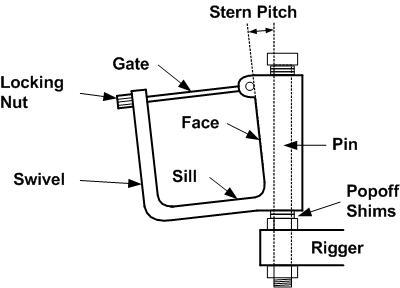
Figure 22:
Oarlock Components
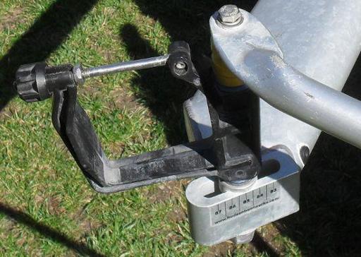
Figure 23:
Oarlock
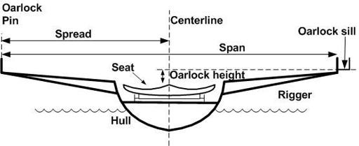
Figure 24:
Rigger Dimensions
The spread is the distance from the centerline of the shell to the oarlock pin. It is measured by taking the distance between the outside of the port gunwale and the starboard gunwale, dividing by two, and then adding the distance from the outside of the gunwale to the center of the oarlock pin. The spread is about 81-88 cm. The picture of the oarlock above shows the spread measurement marked on the rigger.
On a scull, the span is the distance between the port oarlock pin and the starboard oarlock pin. The span is about 157-161 cm. On a scull the starboard oarlock is rigged 1-2 cm higher than the port oarlock so that the left hand is above the right hand at the crossover point.
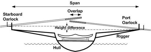
Figure 25:
Oarlock height on Scull
The oarlock height is the distance from the oarlock sill to the top of the seat. This is usually about 13-19 cm. To measure the oarlock height, place a straight edge or spirit level across the gunwales. Then use a tape measure to get the distance from the oarlock sill (the bottom of the oarlock) to the straight edge, and then from the straight edge to the top of the seat.
During the drive, the working face of the sleeve of the oar is driven hard against the face of the oarlock and so the angle of the oarlock face sets the stern pitch to the oar blade. There are two pitch measurements:
- Stern pitch. This is the tilt of the blade of the oar during the drive from the perpendicular towards the stern. This ensures that the blade does not dive too deep during the drive. However if the stern pitch is too large the blade will tend to slip out of the water. Stern pitch is about 4 - 7 degrees and can be measured with a pitch meter (or pitch gauge). The actual pitch of the blade includes the pitch of the oarlock and the pitch of the blade itself. In the US most oar blades have zero pitch, so that the blade of the oar is parallel to flat face of the sleeve, unless the oar is warped. To measure the stern pitch of the oarlock place the pitch meter against the face of the oarlock when it is in the mid-drive position (the oarlock swivel is parallel to the centerline of the boat).
- Lateral pitch. This is also called outboard pitch. This is the tilt of the oarlock pin away from the centerline of the shell. Lateral pitch is about 0-1 degree and cannot usually be changed.
Stern pitch can be changed by making adjustments to the oarlock, or by using an oar with a different pitch. The diagram below shows the sleeve of the oar against the working face of the oarlock. The angle of the working face of an oarlock can be adjusted by inserting different pitch bushings between the oarlock pin and the swivel. Oarlock manufacturers provide rigging manuals that describe the details of how to do this.
