But How Do It Know? - the Basic Principles of Computers for Everyone (12 page)
Read But How Do It Know? - the Basic Principles of Computers for Everyone Online
Authors: J Clark Scott

| | | | | | | |
| | | | | | | |
| | | | | | | |
| | | | | | | |
| | | | | | | |
The simplified diagram looks similar to an OR gate, but it has a double curved line on the input side. The diagram and chart look like this:

| | | |
| | | |
| | | |
| | | |
| | | |
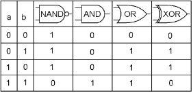
We now have four kinds of gates that take two inputs and make one output. They are NAND, AND, OR and XOR. Here is a chart that makes it pretty simple:

For the four possible input combinations of ‘a’ and ‘b,’ each type of gate has its own set of output states, and the names of the gates can help you remember which is which.
In spite of the fact that everything in the computer is made out of NAND gates, we are not going to be using any NAND gates by themselves in this computer! Now that we have used them to build AND, OR, XOR and NOT gates, and the memory bit, we are done with the NAND gate. Thank you Mr. NAND gate, bye bye for now.
Messing with Bytes
Individual gates operate on bits. Two bits in, one bit out. But the RAM stores and retrieves a byte at a time. And the bus moves a byte at a time. Here in the CPU, we want to be able to work on a whole byte at one time. We want some ‘gates’ that affect an entire byte. In the chapter on the bus, we saw how the contents of a byte can be copied from one register to another. This is usually referred to as moving a byte. Now we are going to see some variations on this.
First we will see three ways that we can change the contents of a byte as it moves from one register to another. Second, we will see four ways that we can take the contents of two bytes, and have them interact with each other to create the contents for a third byte. These are all of the things that computers actually do to bytes. All things ultimately come down to these seven operations.
The Left and Right Shifters
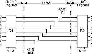
The shifter is very easy to build. It doesn’t use any gates at all, it just wires up the bus a bit oddly. It is done like this:

This shows two registers connected by a right shifter. The shifter is just the wires between the two registers. When the ‘e’ bit of R1 is turned on, and the ‘s’ bit of R2 is turned on and then off, all of the bits in R1 are copied into R2, but they are shifted over one position. The one at the bottom (shift out) can be connected to some other bit in the computer, but is often connected back to the one on the top (shift in) and when that is done, the rightmost bit wraps around to the leftmost bit at the other end of the byte.
A right shifter will change 0100 0010, to 0010 0001.
If ‘shift out’ is connected to ‘shift in,’ a right shift will change 0001 1001 to 1000 1100
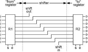
A left shifter will change 0100 0010 to 1000 0100. The left shifter is wired up like so:

Once again, we have bus versions of these drawings. They each have an ‘i’ and ‘o’ bus, and also one input and output bit, like this:


Now of what use is this? The minds of programmers have come up with all sorts of things, but here is an interesting one. Assume that you are using the binary number code. You have the number 0000 0110 in R1. That comes out to the decimal number 6. Now shift that code left into R2. R2 will then be 0000 1100. This comes out to the decimal number 12. What do you know, we have just multiplied the number by 2. This is the basis of how multiplication is done in our computer. How you multiply by something other than 2 will be seen later, but this is how simple it is, just shift the bits. This is similar to something we do with decimal numbers. If you want to multiply something by ten, you just add a zero to the right side, effectively shifting each digit left one position. In the binary system, this only results in multiplying by two because two is what the system is based on.
So that’s the shifter, no gates at all.
The NOTter
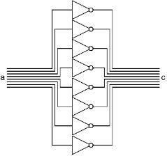
This device connects two registers with eight NOT gates. Each bit will be changed to its opposite. If you start with 0110 1000, you will end up with 1001 0111. This operation is used for many purposes, the first being in some arithmetic functions. We will see exactly how this works soon after we describe a few other things. Another name for a NOT gate is an “inverter,” because it makes the opposite of what you give it, turns it up side down, or inverts it.
