But How Do It Know? - the Basic Principles of Computers for Everyone (14 page)
Read But How Do It Know? - the Basic Principles of Computers for Everyone Online
Authors: J Clark Scott
The left XOR tells us if ‘a’ and ‘b’ are different. If they are, and ‘carry in’ is off, or if ‘a’ and ‘b’ are the same and ‘carry in’ is on, then the right XOR will generate 1 as the sum for the current column. The lower AND gate will turn on ‘carry out’ if both inputs are on. The upper AND gate will turn on ‘carry out’ if ‘carry in’ and one of the inputs are on. This is the simplicity of how computers do addition! Now that we see that it works, we can make a simpler picture of it:

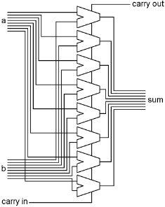
To make an adder that adds two bytes together, we need a one bit adder for each bit of the bytes, with the carry output of each bit connected to the carry input of the next. Notice that every bit has a carry in, even the first bit (the right column.) This is used when we want to add numbers that can be larger than 255.

And the simplified picture of it with bus inputs and output:

The carry output bit of the leftmost (top) column will turn on if the sum of the two numbers is greater than 255, and this bit will be used elsewhere in the computer.
This is how computers do addition, just five gates per bit, and the computer can do arithmetic!
The Comparator and Zero
All of the things we have described above take one or two bytes as input, and generate one byte of output. The shifters and the adder also generate one extra bit of output that is related to their output byte. The comparator only generates two bits of output, not a whole byte.
The comparator is actually built right into the XORer because it can make use of the gates that are already there. The XORer generates its byte of output, and the comparator generates its two bits. These two functions are not really related to each other, it just happens to be easy to build it this way.
What we want the comparator to do, is to find out whether the two bytes on the input bus are exactly equal, and if not, whether the one on the ‘a’ bus is larger according to the binary number system.
The equal thing is pretty simple. XOR gates turn off when the inputs are the same, so if all of the XOR gates are off, then the inputs are equal.
To determine the larger of two binary numbers is a little trickier. You have to start with the two top bits, and if one is on and the other is off, then the one that is on is the larger number. If they are the same, then you have to check the next lower pair of bits etc., until you find a pair where they are different. But once you do find a pair that are different, you don’t want to check any more bits. For example, 0010 0000 (32) is larger than 0001 1111 (31.) The first two bits are the same in both bytes. The third bit is on in the first byte and off in the second, and therefore the first byte is larger. Although the rest of the bits are on in the second byte, their total is less than the one bit that is on in the first byte.
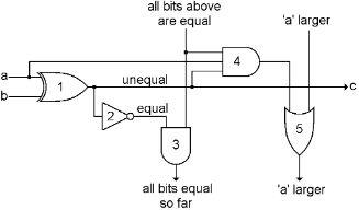
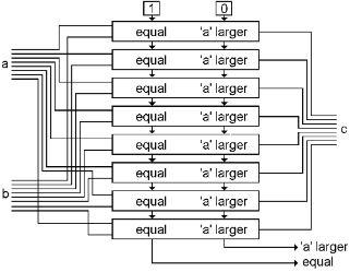
That is what we want to have happen, and it takes five gates times eight positions to accomplish it. Since we are starting with the XORer, we will add four more gates to each position as shown in this diagram. Remember in the adder, we had a carry bit that passed from the lowest bit position up through to the highest bit. In the comparator, we have two bits that pass down from the highest bit position to the lowest.
Here is one bit of the comparator. You can see the original XOR gate, labeled ‘1’, connected up to one bit of each input bus on the left, and generating one bit for the output bus on the right.

If the output of gate 1 is on, that means that ‘a’ and ‘b’ are different, or unequal. We add gate 2, which will turn on when ‘a’ and ‘b’ are equal.
If gate 2 is on at every position, then gate 3 will be on at every position as well, and the bit that comes out of the bottom tells us that the two input bytes are equal.
Gate 4 turns on if three things are true. 1) Bits ‘a’ and ‘b’ are different. 2) Bit ‘a’ is the one that is on. 3) All bits above this point have been equal. When gate 4 turns on, it turns gate 5 on, and that turns on every other gate 5 below this point, and therefore the ‘a larger’ output of the comparator.
When byte ‘b’ is the larger one, both the ‘equal’ bit and the ‘a larger’ bit will be off.
You stack up eight of these bit comparators like the following diagram, with a ‘1’ and ‘0’ connected to the top one to get it started. You still have the XOR function coming out at ‘c,’ and now the two comparator bits at the bottom.

Simplifying again, we will go back to the bus-type XOR diagram, and just add the two new output bits of the comparator.

There is one more thing that we are going to need in our computer that gives us another bit of information. This is a simple gate combination that takes a whole byte as input, and generates only one bit as output. The output bit turns on when all of the bits in the byte are off. In other words, the output bit tells us when the contents of the byte is all zeros.

It is simply an eight input OR gate and a NOT gate. When any of the inputs to the OR gate are on, its output will be on, and the output of the NOT gate will be off. Only when all eight inputs of the OR are off, and its output is therefore off, will the output of the NOT gate be on. The simpler bus representation is shown on the right.
Logic
The subject of thinking has been the object of much study and speculation through the ages. There was a man in ancient Greece named Aristotle who did a lot of work in this area. He must have met a lot of illogical people in his life, because he invented a subject that was supposed to help people think more sensibly.
One of his ideas was that if you have two facts, you may be able to derive a third fact from the first two. In school they sometimes give tests that present two facts, then they give you a third fact and ask whether the third fact is ‘logical’ based on the first two. You may remember questions such as:
If Joe is older than Bill,
And Fred is older than Joe,
Then Fred is older than Bill. True or False?
Or
Children like candy.
Jane is a child.
Therefore Jane likes candy. True or False?
Aristotle called his study of this sort of thing ‘Logic.’
The only relevance this has to our discussion of computers is this word ‘logic.’ Aristotle’s logic involved two facts making a third fact. Many of our computer parts, such as AND gates, take two bits and make a third bit, or eight AND gates take two bytes and make a third byte. And so, the things that these gates do, has come to be known as logic. There may be AND logic and OR logic and XOR logic, but the general term for all of them is logic.
ANDing, ORing and XORing take two bytes to make a third, so they fit this definition of logic pretty well. Shifting and NOTing have also come to be known as logic even though they only take one byte of input to generate their output. The ADDer, although it is has two inputs and is also very logical, somehow is not known to be in the category of logic, it is in its own category, arithmetic.
So all of the ways that we have described above of doing things to bytes come under the heading of ‘arithmetic and logic.’
The Arithmetic and Logic Unit
Now we have built seven different devices that can do arithmetic or logic on bytes of data. We are going take all seven of these devices, put them together in one unit, and provide a method of selecting which one of these devices we want to use at any given time. This is called the “Arithmetic and Logic Unit,’ or “ALU” for short.