But How Do It Know? - the Basic Principles of Computers for Everyone (18 page)
Read But How Do It Know? - the Basic Principles of Computers for Everyone Online
Authors: J Clark Scott
All we have to do to ‘do something useful,’ like adding R1 to R0, is to connect a few wires in the middle, as shown in this diagram with steps four, five and six. Each step causes something to happen to some of the parts that are shown in the CPU diagram. Each step is connected to one ‘enable’ on the left, and one ‘set’ on the right, and therefore causes one part to connect its output to the bus, and another part to save what now appears at its input. Step four is wired to R1 ‘enable’ and TMP ‘set.’ Step five is wired to R0 ‘enable,’ and ACC ‘set.’ The ALU ‘op’ bits do not need any connections since the ‘op’ code for ADD is 000. Step six is wired to ACC ‘enable’ and R0 ‘set.’
During step four, R1 is enabled and TMP is set. The contents of R1 travel across the bus (in the CPU diagram) and are captured by TMP.
During step five, R0 is enabled and ACC is set. If we wanted to do something other than ADD, this is the step where we would turn on the appropriate ALU ‘op’ code bits.
During step six, ACC is enabled and R0 is set.
Here is a graph of the steps, showing when each register gets enabled and set.
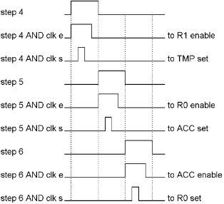
R0 now contains the sum of the original contents of R0 plus R1.
This is how the computer makes things happen in a tightly controlled ballet of bits and bytes moving around inside the machine.
In step seven, the stepper is reset to step 1, where the process repeats. Of course it is not very useful to just do this addition over and over again, even if you start out with the number 1 in both R0 and R1, R0 will get up to 255 pretty quickly.
If the clock in our computer ticks one billion times every second, otherwise known as one gigahertz, and even if we use multiple clock cycles to “do something useful” like this, that means that the computer can do something like this hundreds of millions of times in one second. But we don’t want to just add R1 to R0 over and over again.
Perhaps now that we have added R1 to R0, we want to store that new number to a particular address in RAM, and R2 happens to have that address in it. Again, our processor has all of the connections necessary to do this, and again it will take more than one clock cycle to do it. In step 4, we can move R2 across the bus to MAR. In step 5 we can move R0 across the bus to RAM. That’s all that is needed, just two clock cycles and we’re done.
The wiring for this operation is simpler than the other one, just two enables and two sets.
There are many combinations of things that we can do with the RAM, the six registers and the ALU. We could get a byte from RAM and move it to any of the four registers, we could move any one or two of the registers through the ALU and ADD them, AND them, OR them, XOR them, etc.
We need a way for our CPU to do one thing one time, and a different thing the next time. The control section needs something to tell it what to do in each sequence.
What’s Next?
Now here’s a scary idea. Imagine that the job that an employee does at a fast food restaurant gets broken down into its individual elements. Walk to the counter, say “May I take your order?” listen to the answer, press the “cheeseburger” button on the cash register, etc. Now lets say that there are 256 or less individual actions involved in the job of working at such an establishment. You could then invent a code that would associate one of the states of a byte with each of the individual activities of an employee. Then you could express the sequence of an employee’s actions as a sequence of bytes.
First we make up a code table. We write some codes down the left side of the page. Then we decide what we want those codes to mean, and write those meanings next to the codes. Now we have a list of all of the possible actions that an employee might take, and a code that represents each one of them:
0000 0000 = Walk to the counter
0000 0001 = Say “May I take your order?”
0000 0010 = Listen to the answer
0000 0011 = Press the cheeseburger button
0000 0100 = Press the fries button.
0000 0101 = Press the milk button
0000 0110 = Press the total button
0000 0111 = Collect the money
0000 1000 = Give the customer the change
0000 1001 = Open an empty bag
0000 1010 = Place a cheeseburger in the bag
0000 1011 = Place fries in the bag
0000 1100 = Place a milk container in the bag
0000 1101 = Hand the bag to the customer
1000 0000 = Go to the step number in the right 6 bits.
0100 0000 = If “yes,” go to the step number in the right 6 bits.
0001 0000 = Go home.
Now if we want to describe how the employee is supposed to act, we write a sequence of events that he should follow:
1. 0000 0000 = Walk to the counter.
2. 0000 0001 = Say “May I take your order?”
3. 0100 0010 = If customer is not answering, go to step 2.
4. 0000 0010 = Listen to the answer.
5. 0100 0111 = If customer doesn’t say cheeseburger, go to step 7.
6. 0000 0011 = Press the cheeseburger button.
7. 0100 1001 = If customer does not say fries, go to step 9.
8. 0000 0100 = Press the fries button.
9. 0100 1011 = If customer does not say milk, go to step 11.
10. 0000 0101 = Press the milk button.
11. 0100 1101 = If the customer says that’s all, go to step 13.
12. 1000 0100 = Go back to step 4.
13. 0000 0110 = Press the total button.
14. 0000 0111 = Collect the money.
15. 0000 1000 = Make change and give it to the customer.
16. 0000 1001 = Open an empty bag.
17. 0101 0011 = If order doesn’t include cheeseburger, go to step 19.
18. 0000 1010 = Place a cheeseburger in the bag.
19. 0101 0110 = If order does not include fries, go to step 22.
21. 0000 1011 = Place fries in the bag.
22. 0101 1000 = If order does not include milk, go to step 24.
23. 0000 1100 = Place a milk container in the bag.
24. 0000 1101 = Hand the bag to the customer.
25. 0101 1011 = If it is quitting time, go to step 27.
26. 1000 0001 = Go back to step 1.
27. 0001 0000 = Go home.
I hope nobody ever tries to make the employees of a fast food restaurant learn a code like this. People don’t take well to being so mechanized. But maybe someone will try to staff one of these restaurants with robots someday. In that case, the robots would probably work better using this sort of a code.
And our computer might be able to ‘understand’ a code like this.
The First Great Invention
What we need is some way to do different operations from one stepper sequence to the next. How could we have it wired up one way for one sequence, and then a different way for the next sequence? The answer, of course, is to use more gates. The wiring for one operation can be connected or disconnected with AND gates, and the wiring for a different operation can be connected or disconnected with some more AND gates. And there could be a third and fourth possibility or more. As long as only one of those operations is connected at one time, this will work fine. Now we have several different operations that can be done, but how do you select which one will be done?
The title of this chapter is “The First Great Invention,” so what is the invention? The invention is that we will have a series of instructions in RAM that will tell the CPU what to do. We need three things to make this work.
The first part of the invention is, that we are going to add another register to the CPU. This register will be called the “Instruction Register,” or “IR” for short. The bits from this register will “instruct” the CPU what to do. The IR gets its input from the bus, and its output goes into the control section of the CPU where the bits select one of several possible operations.
The second part of the invention is another register in the CPU called the “Instruction Address Register,” or “IAR” for short. This register has its input and output connected to the bus just like the general purpose registers, but this one only has one purpose, and that is to store the RAM address of the next instruction that we want to move into the IR. If the IAR contains 0000 1010 (10 decimal,) then the next instruction that will be moved to the IR is the byte residing at RAM address ten.
The third part of the invention is some wiring in the control section that uses the stepper to move the desired “instruction” from RAM to the IR, add 1 to the address in the IAR and do the action called for by the instruction that has been put in the IR. When that instruction is complete, the stepper starts over again, but now the IAR has had 1 added to it, so when it gets that instruction from RAM, it will be a different instruction that was located at the following RAM address.
The result of these three parts is a great invention. This is what allows us to make the computer do many different things. Our bus, ALU, RAM and registers make many combinations possible. The contents of the IR will determine what registers are sent to where, and what kind of arithmetic or logic will be done upon them. All we have to do is to place a series of bytes in RAM that represent a series of things that we want to do, one after another.
This series of bytes residing in RAM that the CPU is going to make use of is called a “program.”
The basic thing that happens here is that the CPU “fetches” an instruction from RAM, and then “executes” the instruction. Then it fetches the next one and executes it. This happens over and over and over, millions or billions of times every second. This is the simplicity of what a computer does. Someone puts a program in RAM, and that program, if intelligently designed, makes the computer do something that people find useful.
The stepper in this computer has seven steps. The purpose of step 7 is only to reset the stepper back to step 1. So there are six steps during which the CPU does small things. Each step lasts for one clock cycle. The six steps taken as a whole is called an “Instruction Cycle.” It takes six steps for the CPU to do all of the actions necessary to fetch and execute one instruction. If we assume that our clock ticks at one gigahertz, then our computer will be able to execute 166,666,666 instructions every second.
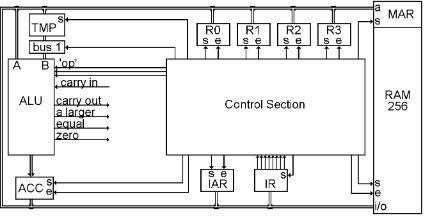
Here is the picture of the CPU with the two new registers added to it. There they are under the Control Section, connected to the bus. The IAR has a ‘set’ and ‘enable,’ the IR only has a ‘set,’ just like TMP and MAR because their outputs are not connected to the bus, so we never need to turn them off.
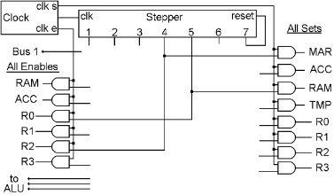
Below is the wiring within the Control Section that does the ‘fetch’ part of the instruction cycle. It uses the first three steps of the stepper and is the same for all types of instructions.