But How Do It Know? - the Basic Principles of Computers for Everyone (20 page)
Read But How Do It Know? - the Basic Principles of Computers for Everyone Online
Authors: J Clark Scott
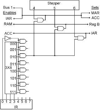
Therefore, the three wires that go to the ALU will be 000 at all times except during step 5 when IR bit 0 happens to be a 1. At such a time, the wires going to the ALU will be the same as bits 1, 2 and 3 of the IR.
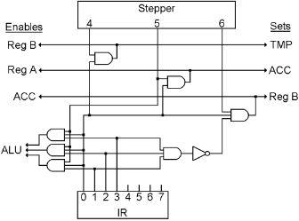
IR bit 0 continues up the diagram, turns right and is connected to one side of three more AND gates. The other sides of these gates are connected to Steps 4, 5 and 6.
The output of the first gate comes on during step 4, and you can see it going to two places. On the left, it enables ‘Reg B’ onto the bus, and on the right, it sets the bus into TMP. This step is actually not necessary for the SHL, SHR and NOT operations, but it doesn’t harm anything, and it would be fairly complicated to get rid of, so for simplicity’s sake we’ll just leave it this way.
The second gate comes on during step 5 (the same step that the ALU gets its orders), and going to the left is a wire that enables ‘Reg A’ onto the bus. The ALU now has one input in TMP, the other input on the bus, and its operation specified by those three ‘op’ wires, so on the right is a wire that sets the answer into ACC.
The third gate turns on during step 6. The wire going to the left enables ACC onto the bus, and the wire going to the right sets the bus into ‘Reg B.’
There is just one special situation in an ALU instruction, and that is when the operation is CMP, code 111. For a compare operation, we do not want to store any results back into ‘Reg B.’ Therefore, there is a three input AND gate connected to IR bits 1, 2 and 3, which is then connected to a NOT gate, and then to a third input on the AND gate that does step 6 of the ALU instruction. So when the operation is 111, the first AND will come on, the NOT will go off, and the output of the Step 6 AND gate will not turn on.
This ALU instruction is now done. Step 7 resets the stepper, which then goes through its steps again, fetching the next instruction, etc, etc.
We are going to invent one more thing here, and that is a shorthand way of writing CPU instructions on a piece of paper. In the Instruction Code, 1000 1011 means “Add R2 to R3,” but it takes a lot of practice for a person to look at 1000 1011 and immediately think of addition and registers. It also would take a lot of memorization to think of it the other way around, that is, if you wanted to XOR two registers, what is the Instruction Code for XOR? It would be easier to write something like ADD R2,R3 or XOR R1,R1.
This idea of using a shorthand has a name, and it is called a computer language. So along with inventing an instruction code, we will also invent a computer language that represents the instruction code. The ALU instruction results in the first eight words of our new language.
Language | Meaning | |
ADD | RA,RB | Add RA and RB and put answer in RB |
SHR | RA,RB | Shift RA Right and put answer in RB |
SHL | RA,RB | Shift RA Left and put the answer in RB |
NOT | RA,RB | Not RA and put the answer in RB |
AND | RA,RB | And RA and RB and put answer in RB |
OR | RA,RB | Or RA and RB and put answer in RB |
XOR | RA,RB | Exclusive OR RA and RB into RB |
CMP | RA,RB | Compare RA and RB |
When a person wants to write a computer program, he can write it directly in the instruction code, or use a computer language. Of course, if you write a program in a computer language, it will have to be translated into the actual instruction code before it can be placed in RAM and executed.
The Load and Store Instructions
The Load and Store instructions are pretty simple. They move a byte between RAM and a register. They are very similar to each other so we will cover both of them in one chapter.
We’ll get to the details of these instructions in a moment, but first we need to have something that tells us when we have a Load or Store instruction in the Instruction Register. With the ALU instruction, all we needed to know was that bit 0 was on. The code for every other type of instruction begins with bit 0 off, so if we connect a NOT gate to bit 0, when that NOT gate turns on, that tells us that we have some other type of instruction. In this computer, there are eight types of instructions that are not ALU instructions, so when bit 0 is off, we will use the next three bits of the IR to tell us exactly which type of instruction we have.
The three bits that went to the ALU in an ALU instruction also go to a 3x8 decoder here in the Control Section. As you remember, one and only one of the outputs of a decoder is on at all times, so we will have AND gates on the outputs to prevent any output from going anywhere during an ALU instruction. But when it is not an ALU instruction, the one output of the decoder that is on, will get through its AND gate, and in turn will be connected to some more gates that make the appropriate instruction work.
In the diagram below, you can see IR bits 1, 2 and 3 going into a decoder which has eight AND gates on its outputs. IR bit 0 has a NOT gate which goes to the other side of those eight AND gates. This decoder is used for the rest of the instructions that our computer will have.
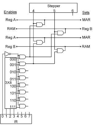
This chapter is about the instructions that use the first two outputs of the decoder, the ones that come on when the IR starts with 0000 or 0001.
The first instruction moves a byte from RAM to a register, this is called the “Load” instruction. The other one does the same in reverse, it moves a byte from a register to RAM, and is called the “Store” instruction.
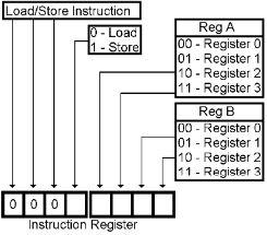
The Instruction Code for the Load instruction is 0000, and for the Store instruction is 0001. The remaining four bits in both cases specify two registers, just like the ALU instruction did, but in this case, one register will be used to select one of the locations in RAM, and the other register will either be loaded from, or stored to, that RAM location.
Step 4 is the same for both instructions. One of the registers is selected by IR bits 4 and 5 and is enabled onto bus. The bus is then set into MAR, thus selecting one address in RAM.
In step five, IR bits 6 and 7 select another one of the CPU registers. For the Load instruction, RAM is enabled onto the bus and the bus is set into the selected register. For the Store instruction, the selected register is enabled onto the bus and the bus is set into RAM.
Each of these instructions only need two steps to complete, step 6 will do nothing.
Here are two new words for our computer language:
Language | Meaning | |
LD | RA,RB | Load RB from RAM address in RA |
ST | RA,RB | Store RB to RAM address in RA |
The Data Instruction
Now here is an interesting instruction. All it does is load a byte from RAM into a Register like the Load instruction, above. The thing that is different about it though, is where in RAM it will get that byte.
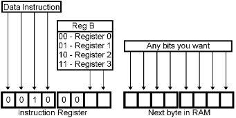
In the Data instruction, the data comes from where the next instruction ought to be. So you could consider that this instruction is actually two bytes long! The first byte is the instruction, and the next byte is some data that will be placed into a register. This data is easy to find, because by the time we have the instruction in the IR, the IAR has already been updated, and so it points right to this byte.
Here is the Instruction Code for the Data instruction. Bits 0 to 3 are 0010. Bits 4 and 5 are not used. Bits 6 and 7 select the register that will be loaded with the data that is in the second byte.
All this instruction needs to do is, in step 4, send IAR to MAR, and in step 5, send RAM to the desired CPU register. However, there is one more thing that needs to happen. Since the second byte of the instruction is just data that could be anything, we do not want to execute this second byte as an instruction. We need to add 1 to the IAR a second time so that it will skip this byte and point to the next instruction. We will do this the same way that it is done in steps 1 and 3. In step 4, when we send IAR to MAR, we will take advantage of the fact that the ALU is calculating IAR plus something at the same time, we will turn on the ‘Bus 1,’ and set the answer into ACC. Step 5 still moves the data to a Register, and in step 6 we can move ACC to IAR.
Here is another new word for our computer language:
Language | Meaning | |
DATA | RB,xxxx xxxx | Load these 8 bits into RB |
The Second Great Invention
The first great invention is this idea of having a string of instructions in RAM that get executed one by one by the CPU. But our clock is very fast, and the amount of RAM we have is limited. What will happen, in far less than a second, when we have executed every instruction in RAM?