But How Do It Know? - the Basic Principles of Computers for Everyone (19 page)
Read But How Do It Know? - the Basic Principles of Computers for Everyone Online
Authors: J Clark Scott

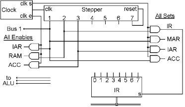
The stepper’s first three steps are shown here, and result in ‘fetching’ the next ‘instruction’ from RAM. Then the rest of the steps ‘execute’ the ‘instruction.’ Exactly what will be done in steps 4, 5 and 6, is determined by the contents of the instruction that was fetched. Then the stepper starts over, fetches the next instruction, and executes it.
The bottom of this diagram includes the Instruction Register. Notice that we have given numbers to the individual bits of the IR, 0 at the left through 7 on the right. We will be referring to the individual bits soon.
Here are the details of exactly how steps 1, 2 and 3 result in fetching an instruction in our little computer:
Step 1 is the most complicated because we actually accomplish two things at the same time. The main thing we want to do is to get the address in IAR over to MAR. This is the address of the next instruction that we want to fetch from RAM. If you look at the wire coming out of step 1 of the stepper, you can see that two of the places it is connected to are the ‘enable’ of IAR and the ‘set’ of MAR. Thus, the contents of IAR will be placed on the bus during ‘clk e’ and set into MAR during ‘clk s.’ Sometime during the instruction cycle, we need to add 1 to the value in IAR, and since IAR is already on the bus, we might as well do it now. If we don’t send anything to the ALU’s ‘op’ bits, they will all be zero, and since 000 is the code for ADD, the ALU will be doing an ADD operation on whatever is on its two inputs, and presenting the answer to ACC. One input comes from the bus, which has IAR on it during this time. If we also turn on the ‘bus 1’ bit during step 1, the other input to the ALU will be a byte with the binary value of 1. If we turn on the ‘set’ of ACC during ‘clk s,’ we will capture the sum of IAR plus 1 in ACC. This just happens to be the address of the instruction that we will want to fetch after we are done with the current one!
Step 2 enables the currently selected byte in RAM onto the bus, and sets it into IR. This is the instruction that we will ‘execute’ in steps 4, 5 and 6 of this instruction cycle. In the diagram, you can see that the wire coming from step 2 is connected to the ‘enable’ of RAM and the ‘set’ of IR.
In step 3, we need to finish updating IAR. We added 1 to it in step 1, but the answer is still in ACC. It needs to be moved to IAR before the beginning of the next instruction cycle. So you can see the wire coming out of step 3 is connected to ‘enable’ of ACC and ‘set’ of IAR.
By the time we get to step 4, the instruction has already been moved from RAM to IR, and now steps 4, 5 and 6 can then do whatever is called for by the contents of IR. When that operation is done and the stepper is reset, the sequence will start over again, but now IAR has had 1 added to it, so the instruction at the next RAM address will be fetched and executed.
This idea of putting a series of instructions in RAM and having the CPU execute them is a great invention.
Instructions
We now have this new register, called the Instruction Register, which contains a byte that is going to tell the Control Section what to do. The patterns that are put into this register have a meaning. Sounds like another code, and indeed, it is. This code will be called the “Instruction Code.”
Since we are building this computer from scratch, we get to invent our own instruction code. We will take the 256 different codes that can be put in the Instruction Register, and decide what they will mean. Then we have to design the wiring inside the control unit that will make these instructions do what we said they would do.
Do you remember the binary number code? We said that it was the closest thing to a ‘natural’ computer code because it was based on the same method we use for our normal number system. Then there was the ASCII code, which was just invented by a bunch of people at a meeting. There is nothing natural about ASCII at all, it was just what those people decided it would be.
Now we have the Instruction Code, which will also be a totally invented code - nothing natural about it. Many different instruction codes have been invented for many different types of computers. We will not study any of them here, nor will you need to study any of them later, unless you are going to go on to a highly technical career where that is necessary. But all Instruction Codes are similar, in that they are what make the computer work. The only Instruction Code in this book will be one that we invent for our simple computer. The most important thing in inventing our Instruction Code, will be how simple we can make the wiring that will make the code work.
How many different instructions could there be? Since the instruction register is a byte, there might be as many as 256 different instructions. Fortunately, we will only have nine types of instructions, and all 256 combinations will fall into one of these categories. They are pretty easy to describe.
All instructions involve moving bytes across the bus. The instructions will cause bytes to go to or from RAM, to or from registers, and sometimes through the ALU. In the following chapters, for each type of instruction, we will look at the bits of that instruction, the gates and wiring necessary to make it work, and another handy code we can use to make writing programs easier.
The Arithmetic or Logic Instruction
This first type of instruction is the type that uses the ALU like our ADD operation earlier. As you recall, the ALU has eight things it can do, and for some of those things it uses two bytes of input, for other things it only uses one byte of input. And in seven of those cases, it has one byte of output.
This type of instruction will choose one of the ALU operations, and two registers. This is the most versatile instruction that the computer can do. It actually has 128 variations, since there are eight operations, and four registers, and you get to choose twice from the four registers. That is eight times four times four, or 128 possible ways to use this instruction. Thus this is not just one instruction, but rather it is a whole class of instructions that all use the same wiring to get the job done.
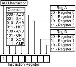
Here is the Instruction Code for the ALU instruction. If the first bit in the Instruction Register is a 1, then this is an ALU instruction. That’s the simplicity of it. If the first bit is on, then the next three bits in the instruction get sent to the ALU to tell it what to do, the next two bits choose one of the registers that will be used, and the last two bits choose the other register that will be used.

Therefore, the ALU Instruction (1), to add (000) Register 2 (10) and Register 3 (11), and place the answer in Register 3, would be: 1000 1011. If you placed this code (1000 1011) in RAM at address 10, and set the IAR to 10, and started the computer, it would fetch the 1000 1011 from address 10, place it in IR, and then the wiring in the control section would do the addition of R2 and R3.
If you choose a one input operation, such as SHL, SHR or NOT, the byte will come from the Reg A, go through the ALU, and the answer will be placed in the Reg B. You can choose to go from one register to another such as R1 to R3, or choose to go from one register back into the same one, such as R2 to R2. When you do the latter, the original contents of the register will be replaced.
For two input operations, Reg A and Reg B will be sent to the ALU, and the answer will be sent to Reg B. So whatever was in Reg B, which was one of the inputs to the operation, will be replaced by the answer. You can also specify the same register for both inputs. This can be useful, for instance, if you want to put all zeros in Register 1, just XOR R1 with R1. No matter what is in R1 to begin with, all bit comparisons will be the same, which makes the output of all bits zeros, which gets placed back into R1.
The CMP operation takes two inputs and compares them to see if they are equal, and if not, if the first one is larger. But the CMP operation does not store its output byte. It does not replace the contents of either input byte.
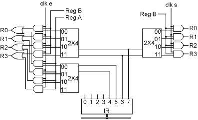
The wiring in the Control unit for the ALU instruction is pretty simple, but there is one extra thing that will be used by many types of instructions that we need to look at first. This has to do with the registers. In “Doing Something Useful Revisited,” we used two registers. To use them, we just connected the AND gate for each register to the desired step of the stepper. This was fine, but in the ALU instruction, and many others, there are bits in the instruction register that specify which register to use. Therefore we don’t want to wire up directly to any one register, we need to be able to connect to any of the registers, but let the bits in the instruction choose exactly which one. Here is the Control Section wiring that does it:

Look at the right side first. When we want to set a general-purpose register, we connect the proper step to this wire that we will call ‘Reg B.’ As you can see, ‘clk s’ is connected to all four AND gates. ‘Reg B’ is also connected to all four AND gates. But these four AND gates each have three inputs. The third input to each AND gate comes from a 2x4 decoder. You remember that one and only one output of a decoder is on at any given time, so only one register will actually be selected to have its ‘set’ bit turned on. The input to the decoder comes from the last two bits of the IR, so they determine which one register will be set by this wire labeled ‘Reg B.’ If you look back at the chart of the bits of the ALU Instruction Code, it shows that the last two bits of the instruction are what determine which register you want to use for Reg B.
The left side of the picture is very much like the right side, except that there are two of everything. Remember that in an ALU instruction such as ADD, we need to enable two registers, one at a time, for the inputs to the ALU. The last two bits of the instruction are also used for ‘Reg B’ on the left, and you can see that ‘clk e,’ ‘Reg B’ and a decoder are used to enable one register during its proper step. Bits 4 and 5 of the IR are used to enable ‘Reg A’ during its proper step, using a separate decoder and a wire called ‘Reg A.’ The outputs of these two structures are ORed together before going to the actual register enable bits. We will never select ‘Reg A’ and ‘Reg B’ at the same time.
What happens when the instruction that has been fetched begins with a 1? That means that this is an ALU instruction, and we need to do three things. First we want to move ‘Reg B’ to TMP. Then we want to tell the ALU which operation to do, put ‘Reg A’ on the bus and set the output of the ALU into ACC. Then we want to move ACC to ‘Reg B.’
Bit 0 of the IR is the one that determines if this is an ALU instruction. When Bit 0 is on, the things that Bit 0 is wired up to make all of the steps of an ALU instruction occur.
The next diagram shows the eight gates and the wires that are added to the Control Section that make steps 4, 5 and 6 of an ALU instruction do what we need them to do.
In the diagram below, just above and to the left of the IR, there are three AND gates. The outputs of these gates go to the three ‘op’ wires on the ALU that tell it which operation to do. Each of these three AND gates has three inputs. One input of each gate is wired to bit 0 of the IR. A second input of each gate is wired to step 5 from the stepper. The remaining input of each gate is wired to bits 1, 2 and 3 of the IR.