But How Do It Know? - the Basic Principles of Computers for Everyone (22 page)
Read But How Do It Know? - the Basic Principles of Computers for Everyone Online
Authors: J Clark Scott
In step 5, we move ACC to IAR so we are ready to fetch the next instruction IF we don’t jump.
Step 6 is where the “decision” is made. We will move the second byte of the instruction from RAM to IAR IF the third input to that AND gate is on. That third input comes from an OR gate with four inputs. Those four inputs come from the four Flag bits after being ANDed with the last four bits of the Jump If instruction in IR. If, for instance, there is a ‘1’ in the ‘Equal’ bit of the instruction, and the ‘Equal’ Flag bit is on, then the jump will occur.
Here are more words for our computer language. ‘J’ means Jump, ‘C’ means Carry, ‘A’ means A is larger, ‘E’ means A Equals B and ‘Z’ means that the answer is all Zeros. Here are the words of the language that test a single Flag:
Language | Meaning | |
JC | Addr | Jump if Carry is on |
JA | Addr | Jump if A is larger than B |
JE | Addr | Jump if A is Equal to B |
JZ | Addr | Jump if the answer is Zero |
You can also test more than one flag bit at the same time by putting a 1 in more than one of the four bits. Actually since there are four bits, there are 16 possible combinations, but the one with all four bits off is not useful because it will never jump. For the sake of completeness, here are the rest of the possibilities:
Language | Meaning | |
JCA | Addr | Jump if Carry or A larger |
JCE | Addr | Jump if Carry or A Equal B |
JCZ | Addr | Jump if Carry or answer is Zero |
JAE | Addr | Jump if A is larger or Equal to B |
JAZ | Addr | Jump if A is larger or answer is Zero |
JEZ | Addr | Jump if A Equals B or answer is Zero |
JCAE | Addr | Jump if Carry or A larger or Equal to B |
JCAZ | Addr | Jump if Carry or A larger or Zero |
JCEZ | Addr | Jump if Carry or A Equals B or Zero |
JAEZ | Addr | Jump if A larger or Equal to B or Zero |
JCAEZ | Addr | Jump if Carry, A larger, Equal or Zero |
The Clear Flags Instruction
There is one annoying detail that we need to have here. When you do addition or shifting, you have the possibility of getting the carry flag turned on by the operation. This is necessary, we use it for the Jump If instruction as in the previous chapter.
The Carry Flag is also used as an input to the addition and shift operations. The purpose of this is so you can add numbers larger than 255 and shift bits from one register to another.
The problem that arises is that if you are just adding two single-byte numbers, you don’t care about any previous Carry, but the Carry Flag may still be set from a previous operation. In that case, you might add 2+2 and get 5!
Bigger computers have several ways to do this, but for us, we will just have a Clear Flags Instruction that you need to use before any adds or shifts where an unexpected carry bit would be a problem.
Here is the Instruction Code for this instruction. Bits 4, 5, 6 and 7 are not used.
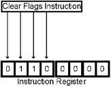
The wiring for this is very simple and a bit tricky. We will not enable anything onto the bus, thus it and the ‘A’ ALU input will be all zeros. We will turn on ‘Bus 1’ so the ‘B’ input is 0000 0001. We won’t send an operation to the ALU, so it will be in ADD mode. The ALU, therefore, will be adding 0 and 1, and there may be a carry input. The answer then will be either 0000 0001 or 0000 0010. But there will be no carry output, the answer is not zero and B is larger than A so ‘equal’ and ‘A larger’ will both be off. We ‘set’ the Flag Reg at this time while all four Flag bits are off.
Here is another word for our language.
Language | Meaning |
CLF | Clear all Flags |
Ta Daa!
We have now wired up the Control Section of our CPU. As a result, we can place a series of instructions in RAM, and the Clock, Stepper, Instruction Register and wiring will fetch and execute those instructions. Here is the entire control section:
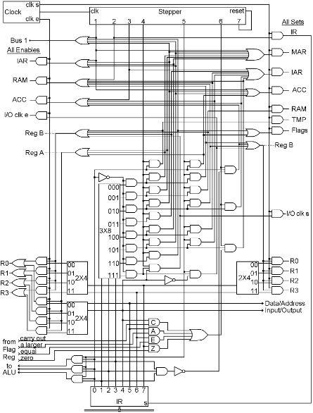
Yes, this looks pretty complicated, but we have looked at every part of it already. The only thing we had to add were some OR gates because most of the ‘enables’ and ‘sets’ need multiple connections. This actually has a lot fewer parts than the RAM, but that was much more repetitive. Most of the mess here is just getting the wires from one place to another.
The byte that is placed in the Instruction Register causes a certain activity to occur. Each possible pattern causes a different activity. Therefore, we have a code where each of the 256 possible codes represents a different specific activity.
As mentioned, this is called the Instruction Code. Another name for it is “machine language,” because this is the only language (code) that the machine (computer) “understands.” You “tell” the machine what to do by giving it a list of orders you want it to carry out. But you have to speak the only language that it “understands.” If you feed it the right byte-sized patterns of ons and offs, you can make it do something that will be useful.
Here are all of the Instruction Codes and our shorthand language brought together in one place.
Instruction Code | | Language | | Meaning |
1000 | rarb | ADD | RA,RB | Add |
1001 | rarb | SHR | RA,RB | Shift Right |
1010 | rarb | SHL | RA,RB | Shift Left |
1011 | rarb | NOT | RA,RB | Not |
1100 | rarb | AND | RA,RB | And |
1101 | rarb | OR | RA,RB | Or |
1110 | rarb | XOR | RA,RB | Exclusive OR |
1111 | rarb | CMP | RA,RB | Compare |
0000 | rarb | LD | RA,RB | Load RB from RAM addr in RA |
0001 | rarb | ST | RA,RB | Store RB to RAM addr in RA |
0010 | 00rb xxxxxxxx | DATA | RB,Data | Load these 8 bits into RB |
0011 | 00rb | JMPR | RB | Jump to the address in RB |
0100 | 0000 xxxxxxxx | JMP | Addr | Jump to the addr in the next byte |
0101 | Caez xxxxxxxx | JCAEZ | Addr | Jump if any tested Flag is on |
0110 | 0000 | CLF | | Clear all Flags |
Believe it or not, everything you have ever seen a computer do, is simply the result of a CPU executing a long series of instructions such as the ones above.
A Few More Words on Arithmetic
We don’t want to spend a lot of time on this subject, but the only thing that we have seen so far that looks like arithmetic is the adder, so we will look at simple examples of slightly more complex arithmetic. Not to teach you how to act like a computer, but just to prove to you that it works.
Here is how you do subtraction. It is done with the adder and the NOT gates. If you want to subtract R1 from R0, first you NOT R1 back into itself. Then you add 1 to R1, then you Add R0 to R1.
This shows an example of subtracting 21 from 37:
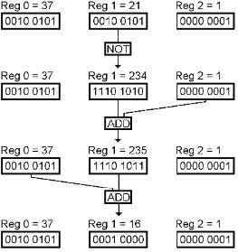
The last step is adding 37 + 235, the answer of which should be 272. But a single register cannot hold a number larger than 255. Therefore the adder turns on its Carry bit, and the eight bits remaining of the answer are 0001 0000, which is 16, the correct answer for 37 minus 21.