Mac Hacks (35 page)
. Use a Wiimote with Your Mac
Have
an extra Wii Remote lying about? Don’t let it collect
dust—use it to run your Mac!
In
[Hack #50]
, you learned how
to mount an iMac to a VESA mount. A moveable iMac turns out to be great
for a lot of different reasons but, as you’d expect, there are unintended
consequences. Getting the iMac out of the way was nice for drawing and
desk-space considerations, and it also made it nice to watch movies on
from a distance. But having to use a mouse or a trackpad while you’re
watching a movie just screams paste-eater, so you need alternative.
There are a few different ways to communicate with your Mac, but
anything involving a cable won’t work for this situation. That leaves
spoken commands (which I’ve tried and have found to be less than ideal),
control it via WiFi (certainly possible), and controlling it with a
Bluetooth device. The idea of controlling your Mac with a Bluetooth device
isn’t far-fetched at all—you already do it if you use a wireless keyboard,
trackpad, or mouse.
The Apple-supplied kit is straight out—keyboards, trackballs, and
mice are designed to sit flat and be used in close proximity to the
computer, and the Apple Remote...ugh. What would be ideal is something
that could be used farther away from the iMac.
Note: You can use your wireless keyboard or trackpad farther away
from the computer if you’re determined to do so. At Mac Hack Labs, we
were able to use a trackpad 48 feet away from an iMac and then ran out
of basement.
What
controller uses Bluetooth, is specifically designed for
pointing at the screen, and just happens to be available to fathers who
don’t mind stealing from their sons? You guessed it: a Wiimote! With a
name that cute, you might be tempted to jettison the idea, but don’t—it
works surprisingly well. Let’s get your Mac working with your repurposed
Bluetooth controller.
Before trying to make the Wiimote work with your Mac, it’s a good
idea to see if it already does. Open the back of the Wiimote and push the
orange button. Choose “Set up Bluetooth Device” from your Mac’s menu bar,
and you’ll see an entry called Joystick; select that option and your Mac
will attempt to pair with your Wiimote. Since this hack doesn’t end here,
you can probably guess what happens (
Figure 11-21
).
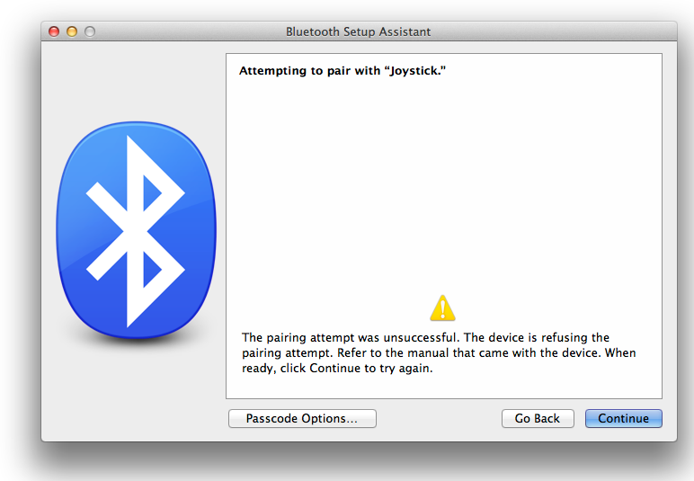
unsuccessful” message on this screen. This step lets you know that your
Mac can get the Bluetooth signal that the Wiimote is sending out. Don’t
think of it as a failure, think of it as a promising sign!
After your Mac tells you that the Wiimote refused to pair with your
computer, you need a way to trick the Wiimote into thinking it’s okay to
pair with your Mac. At this point, you could write a program to do just
that, but happily you don’t need to go to all that effort: someone has
already gone to the trouble and written DarwiinRemote. Point your browser
to
this
page
to download the program.
Warning: If you’re using Mountain Lion, be sure to get the version
10.8 of DarwiinRemote. Mountain Lion doesn’t work with earlier versions
of DarwiinRemote, so if you install one of those versions instead,
you’ll just end up frustrated.
Once you download the
.dmg
file, double-click
it and fire it up. You’ll be told to pair the Wiimote with your Mac by
pushing the 1 and 2 buttons simultaneously (just like you do with the
Wii). Once the pairing is made, you’re off to the races (
Figure 11-22
).
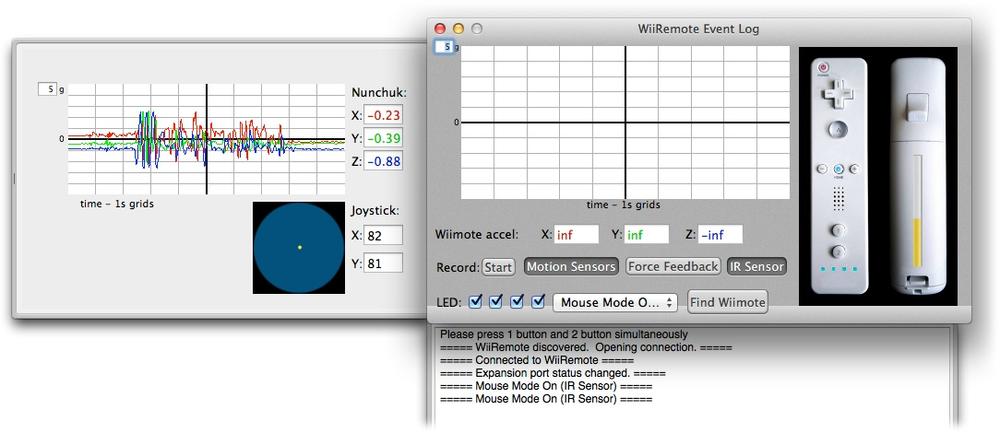
joystick, the accelerometer in the nunchuck, and even the balance board
if you wish.
Once everything is running, you’ve got some choices to make. In this
case, the point was to use the Wiimote as a mouse, so use DarwiinRemote’s
drop-down menu to choose “Mouse Mode On (Motion).” Congratulations—you now
have a horrible mouse! (Well, at least when I tested it, it was horrible).
It’s a great time to remember that Command-Q quits a program, because if
you try to mouse to DarwiinRemote’s menu to quit, you’ll have to fight the
Wiimote to get there.
This is a pretty big problem, but recall that you set the mouse
(technically, the Wiimote) to Motion mode. This means the Wiimote is
relying solely on its built-in accelerometer. But the Wiimote was designed
to use the accelerometer
and
infrared sensors. This
is no problem if you have a Wiimote sensor bar lying around. Just hook it
to the Wii, power it up, and then place the sensor bar in front of your
Mac. In DarwiinRemote, change “Mouse Mode On (Motion)” to “Mouse Mode On
(IR)” and you’ll be able to use your Wiimote as a mouse!
While adding the sensor bar solves that problem, it’s still not
really a workable solution. You have to have a Wii near your computer, you
have to keep the Wii plugged in, and the fact that this solution involves
a cord violates the spirit of
[Hack #50]
. What we need is a wire-free way
to power the sensor bar. The sensor bar works on 5 volts, but it’s just 10
infrared lights, so its power tolerances aren’t super tight. The loose
tolerances allow a few methods to attack the problem. If you look very
closely at the plug end of the sensor bar cable, you’ll see two contacts
(
Figure 11-23
).
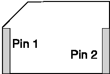
outer shield is not used. It also might be the simplest pin out in
history.
With a lot of patience and some luck, you can cram a couple of wires
onto the contacts, hook those up to a battery (I used a 9-volt battery),
and power the sensor bar in a non-destructive manner. Or, if you don’t
mind destroying the sensor-bar cable, you can attach it to a USB plug and
use power from your Mac to power it. Alternatively, you can buy a 9-volt
connector and wire it in to the sensor-bar cable. In the future, the
current configuration will be changed out for the USB-powered option, but
until the current 9-volt battery runs out, the super-ugly hacked-together
version will work (why waste a battery?).
Once you’ve got control of your Wiimote and everything is working as
you expect, it’s time to make some changes so things work even better!
Select DarwiinRemote→Preferences, and you’ll be greeted by a page with
multiple panes (
Figure 11-24
). These panes let
you assign keys, create a new profile by clicking the Add button, and even
manually calibrate your Wiimote “mouse.”
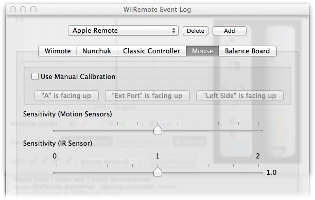
control just about every aspect of the Wiimote by using the various tabs
shown here.
When everything is set up the way you want it, you can put your
mouse away and control your Mac from up to 16 feet away using the Wiimote.
(Your Mac will likely receive the Wiimote’s signal from a greater
distance, but 16 feet was the max distance used in the design of the
Wiimote, so beyond that you’re kind of taking your chances. Plus, unless
you make the cursor really big or are part eagle, you won’t be able to see
what you’re doing
anyway.)
. Turn Your MacBook into a Tablet
Wishing
for something as portable as an iPad with the power of a
MacBook? You can get just that with some bold hacking and ingenious
modding. (This device even runs Flash!)
The era before the iPad/iPhone and tablet boom was a time when
people were longing for a tablet Mac. A lot of people, and some companies,
created tabletized Macs before the iPad showed up. Those projects helped
to fill a gap in a Apple’s offerings—after all, Apple hadn’t released
anything truly handheld oriented since the Newton MessagePad. (In honor of
that device, I call this project the MessagePad.) Every year, there were
rumors of the next iTablet. And at the time, it was fairly difficult
(though far from impossible) to procure OS X/9–compatible touch overlays
for cheap.
This project was on my list for ages. And now I’ve finally finished
it! There certainly is a giant continuum of portable, touch-oriented
devices that have existed over the years, and where this one fits in, I’m
not sure. But if these features seem compelling and you have the budget,
give this hack a shot:
Resistive 13-inch touchscreen (as opposed to a capacitive one;
you’ll learn the difference in a sec)User-facing iSight camera
Rear-facing iSight camera with colored flash (optional)
Teensy 2.0 USB development board
32 GB SSD
Sleep switch
mDVI port
USB 2.0 port
FireWire port
Gigabit Ethernet port
Line in
Built-in speakers
That’s a nice feature set, but it comes at a price: this tablet is
heftier than an iPad. On the other hand, you can do everything on it that
you can do with a Mac.
Warning: This project entails doing a lot of (nearly) irreversible
things to your expensive computer. Undoing these changes would require
replacing a nice pile of parts. Know this going in.
As mentioned in
[Hack #49]
, it’s important to
remember that just because computers have the same model name
doesn’t
mean they share parts. For example, core
Duo MacBooks have a completely different motherboard mount and fan vent
strut than other MacBook models. And 2009 Core 2 Duos changed the
optical drive connector, and who knows what else. The point is, they’re
all different, so be sure to get parts specific to your Apple order
number or design year.
Mactracker
is a wonderful resource for this.
While this project is nowhere near as dangerous as my Macbook Dye
Project (see
[Hack #49]
),
it’s still dangerous. Working with Dremels, sharp cutting tools, drills,
routers, and other equipment can be very hazardous. I don’t cover all of
the safety steps here, but goggles, dust masks, gloves, clamps, and an
apron help
a lot
. Remember:
caution and
planning are the best defenses against accidents
. These
things can hurt you and/or people around you. I’m not responsible if you
drill through your favorite desk, your pinky toe, your cat, your laptop,
your new TV, or anything else that may happen based on what you read
here. You can also ruin your laptop, if you’re not careful (which is
more important than that life and limb stuff, right? Who needs limbs?).
Be more careful than I was and you’ll be fine! In other words: do as I
say, and not as I do.
If none of that scared you, then you are an enterprising
individual and you should high-five yourself because you’ve got what it
takes to tackle this project. Let’s get started!
It’s best to gather all the supplies before you begin. You
could
acquire them as you progress, but that would
slow you down quite a bit. Most of these items are easy to find, and
I’ve included links for the more difficult ones:
Pre-unibody white MacBook (I used the 2007 MacBook 3,1 – Core
2 Duo, GMA X1300)13.3-inch 16:9 eGalax Touch Overlay (or use the overlay of
your choice; it’s wise to keep the same aspect ratio)Normally open push-button switch
Normally open SPST toggle switch
iMac G5/Intel iSight board
“Thin” USB hub (Try to find a hub that supports high-power
devices; these usually have nice-sized capacitors in them)8 GB flash drive
22 AWG multistrand wire
28 AWG single-strand wire
Spare set of MacBook lid magnets (or any flat neodymium magnet
that will fit)Electrical tape
Gorilla Glue
Any Dremel with cutting, buffing, and smoothing discs
Cake (to eat in celebration when you’re done!)
If you decide to include the optional rear-facing flash, you’ll
also need:
ShiftBrite
module
. I used a 1.0 module, but I’m sure a 2.0 module would
work just fine.
Once you start cutting into your
MacBook’s lid, there’s no going back
. Measure everything
roughly 4,000 times before you make your cuts. (One exception:
there’s some tolerance for error on the viewport for the LCD, so
don’t let it bother you if it’s slightly off. Just do your absolute
best to make it straight, and the Sugru will do the rest. Don’t
worry: this advice will make sense later.) The point is, measure a
million times, cut once.The touchscreen isn’t a perfect
fit
. With the touchscreen overlay I used there’s a ~25 px
cutoff on the bottom of the screen. I’ve tried to mitigate this
using forced resolutions in OS X, but the LCD’s firmware is
programmed to crop to available area, so my efforts have been
fruitless. That said, if you position the overlay so the blackout
area is on the bottom, there’s very little loss of screen real
estate. Take your time and do your research, and you might be able
to find a better option.The touchscreen has a couple major
drawbacks
. The touchscreen I used for this project is
resistive
, whereas the touchscreens you’re
likely most used to (iPhones, iPads, etc.) are
capacitive
. Resistive touchscreens can only
accept input from a single point of touch at a time (so no
multitouch), they’re affected by heat, they can’t be bent or crushed
without breaking, and they have low resolution. So take your
expectations for the overlay and take them down a couple of notches.
It’s relatively difficult to do precision work with this kind of
screen (so kiss those dreams of running Photoshop, or using this as
a serious drawing tablet, goodbye), but it’s well suited for
day-to-day work and gaming (Plants versus Zombies is awesome on
here, for example).Don’t try and use the Bluetooth’s USB
port directly
. This port and the Bluetooth board itself
are both 3.3 V, so it won’t properly power any of the hubs or
devices commonly available.
First off, remove your Macbook’s display and optical drive. I’m
not going to detail taking apart the computer here—I’ll
leave that to the mages at
iFixit
. Their take-apart
guides are the absolute best anywhere. Identify the Mac you’re using,
follow the appropriate guide, and you’ll never lose your way.
Warning: Parts are very easy to crack or deform, so take time
disassembling the computer. You can disassemble
every
part on the computer without major force.
If you’re forcing something, it’s likely you’ve forgotten a screw.
Adhesive is used to secure some parts, such as the Apple logo, which
requires a slight bit of force to remove. You should use a heatgun to
loosen the adhesive and pop it out. Don’t try and force it out or you
will
crack the lid (I speak from
experience).
Set the bottom case, battery, and their assorted counterparts
aside for now, and focus on the display. The basic idea is to turn the
LCD around in the lid and use the lid as our new display bezel. To get
started, remove all the guts from the display housing, but leave the lid
magnets alone, and save the sleep magnet for another project or your
fridge. Once you’ve got the LCD out with its mounting frame, remove the
mounting frame from the LCD by unscrewing the handful of small screws
around the edge. Then remove the iSight camera from its aluminum frame,
but leave its plastic bezel attached. Finally, remove the hinges from
the lid (where we’re going, we don’t
need
hinges).
The lid should now be (mostly) empty.
Place the frame back into the lid, but don’t screw it in. Use the
frame as your guide for marking where you have to make the cuts in the
lid. The goal is to turn the LCD around and reattach it to its normal
frame, giving it a nice stable mount, and relieving us of some tedious
fabrication work. Once you’ve made the markings where to cut,
triple-check that it looks right (see
Figure 11-25
). If so, cut the
lid where you marked. Then check fitment of the LCD in the new hole.
(Using the frame as the cutting guide will actually leave a small border
of dead LCD space. Later on, we’ll use the Sugru to fill this gap and
add stability to the touch overlay.)
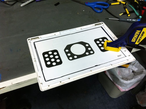
cutting. This will be the bezel for the MacBook MessagePad so you’ll
be looking at it a lot.
Next, choose the orientation of your touch overlay, and figure out
where the ribbon cable will have to surface. Then use your Dremel to
remove any plastic standoffs that may be in the way of where the ribbon
will go. Make sure you smooth it out, as those ribbons are very fragile.
You may have to make a small notch in the LCD mounting frame to allow
the ribbon to pass through. Once that’s done, attach your LCD to its
original mounting frame in the reverse direction, so it faces the new
hole in the lid. There are a couple ways of doing this. You can drill
holes in the LCD’s mounting frame (because none of the original holes
will match up) and then use the LCD’s original screws to reattach it, or
you can Gorilla Glue it to the frame in the reverse direction. I chose
the latter, but I recommend the former (another “Do as I say, not as I
do” moment).
Now, while the glue is drying (or you’re reveling in your
frame-drilling prowess), use your smoothing wheel to thin out the
plastic around the inside of your new
bezelid
.
(Awesome word, yeah? Bezel+lid.) The touch overlay cannot be smooshed
between the bezel and the LCD, and presently there isn’t enough
clearance to fit it in there. So shave 1 mm or so off of that bezelid
around the overlay, and then you should be good to go. If in doubt, test
your overlay and LCD in place, once the glue is dry. If the touch seems
to be wonky or sticking to one side, there’s likely to be a crease. Test
and test again (
Figure 11-26
).
properly when everything is assembled. Don’t rush this step or you’ll
regret it later.
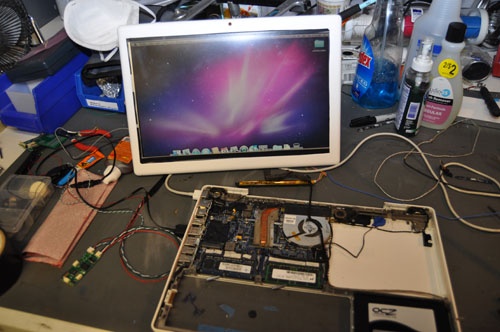
Once there seems to be enough clearance, tape your overlay to your
LCD+frame. (I ran tape around the edges, and added a strip over the
“dead” area on the bottom of the LCD to protect it.) Make sure the
overlay is stable and in the right position on your LCD. (This is where
the overlay’s shortcomings become apparent; it’s too short vertically to
fill in.) Next, mount the LCD inside the bezelid with the taped-on
overlay. From the front of the bezelid, you can see the electrical tape
boarder now. These are the areas where you should apply your Sugru (it
can be white or whatever color you want) to create a nice soft border,
and you can taper the border so that you can reach the very edges of the
LCD to touch. It’s a hard thing to describe, but just use your best
judgment. Sugru is a lot like Play-Doh, only it hardens into a permanent
rubber-like form. It will firmly hold the touch overlay in place inside
the bezelid, and be nice and soft on the user’s fingers.
Now, test your overlay again. Looking good? Try the 25 pt
Calibration inside the eGalax Touch menu. Better? Awesome. The hard part
is almost done, so give yourself a second to be proud of your work. Now
let’s mount the user-facing iSight camera. The iSight can’t fit in its
previous position due to the framing change. So, instead, we’ll use the
part of the frame where the hinges were previously mounted as this area
has ample space. Use your Dremel to smooth out a surface dead center of
the “bottom” of the bezelid. Then find a drill bit the size of the
iSight lens and drill dead center. This is going to take a little trial
and error. Next, remove the plastic bezel from the iSight. The lens can
float freely attached to its PCB, or be disconnected; the microphone
will stay attached to the bezel. Align the bezel in the smoothed area
with the hole you drilled for the lens, and then glue it in place. When
it’s dry, pop in the iSight (
Figure 11-27
) and you’re good to
go! You should probably tack down the iSight PCB with some tape, screws,
or glue. Exactly how to secure your iSight PCB is a decision that I’ll
leave up to you.
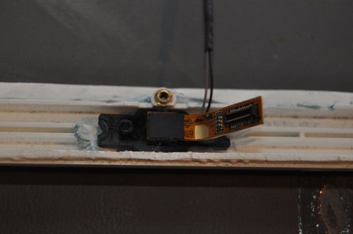
all the cool functionality of the iSight. Plus, you paid for it when
you bought your MacBook!
One last part for the new top case, and then you’re done! Take
your spare set of lid (neodymium) magnets and glue them in place in the
two magnet-less corners of the lid. Try to align them against the other
two magnets mounted in the bezelid’s frame. (We’re going to use these
later to attach the top case to the bottom case.) Magnets make it easier
to do maintenance in the future, but also provide a strong bond for
carrying around. The aluminum iMacs, for example, are held together by
magnets. Kinda neat, huh?
Top case—
done!
Time for some cake! But not
too much—don’t want to go into a sugar coma (yet). Now, set your awesome
new top case/bezelid/thingy aside.
Bottom case time. This is a good opportunity to take off your heat
sink, replace your thermal grease, and clean out your fans. Once that’s
done, remove the logic board from the bottom case and place it on a soft
surface (foam works well) until you’re ready to do your soldering. At
this point, I attached my power button and sleep toggle to the solid
metal area in the fan vent, near the Bluetooth board. It’s notable
because air can’t pass through it, so use your Dremel or drill to cut
holes in this area the right size for the switches you chose. Then screw
your button and switch in, and fill in any gaps with Sugru. Take care
not to bend the metal strut that’s built into the bottom case. After
cutting this, make sure to thoroughly clean the bottom case, as this cut
produces aluminum dust, which is very bad for the logic board and
electronic components.
We won’t be re-using the optical drive, and chances are yours
doesn’t work anymore anyway. (They’ve got a shelf life of 2 years in
these machines.) If you’re looking to save weight and don’t care about
the rear-facing camera, 8 GB recovery drive, or Teensy, you can skip the
hub installation, tie your touch-driver board into your
Trackpad/Keyboard USB port, route the power and sleep buttons, and
you’re done! But, that way isn’t anywhere near as much fun.
Now, by far the hardest part of this is soldering onto the
trackpad USB connector. That’s where we’ll pull signals for the power
button and the USB hub to host our other add-on devices. Use a fine
soldering tip, watch a bunch of how-to soldering YouTube videos, and
take your time. To pull this off, you’ll need a diagram of
the pinout
. The power button is active when it’s
pulled LOW to ground. So, whenever you ground that pin, the computer
will boot. Attach the power-signal wire to one side of your power
button, and then attach the other side of the button to a grounded area.
USB ground works just fine. Test!
The other four pins listed are an internal USB port used by the
MacBook’s trackpad and keyboard. We’re going to take that and attach it
to a hub to add some devices. Solder your hub onto those pins and place
it into your empty optical drive bay. Use small wires so you can route
them in the lanes on the logic board, and double-check the pins to be
sure they’re matched properly (
Figure 11-28
). Once that’s
done, boot it up and test. Hub works? Rock on. (An alternative method
for this part is to use one of the external USB ports. I won’t detail
that process here, but those pins are a lot easier to solder
onto.)

necessary but it does make the final product much better in day-to-day
usage.